Flashing LEDs
Step 2: Assembling the Project
Connecting the parts
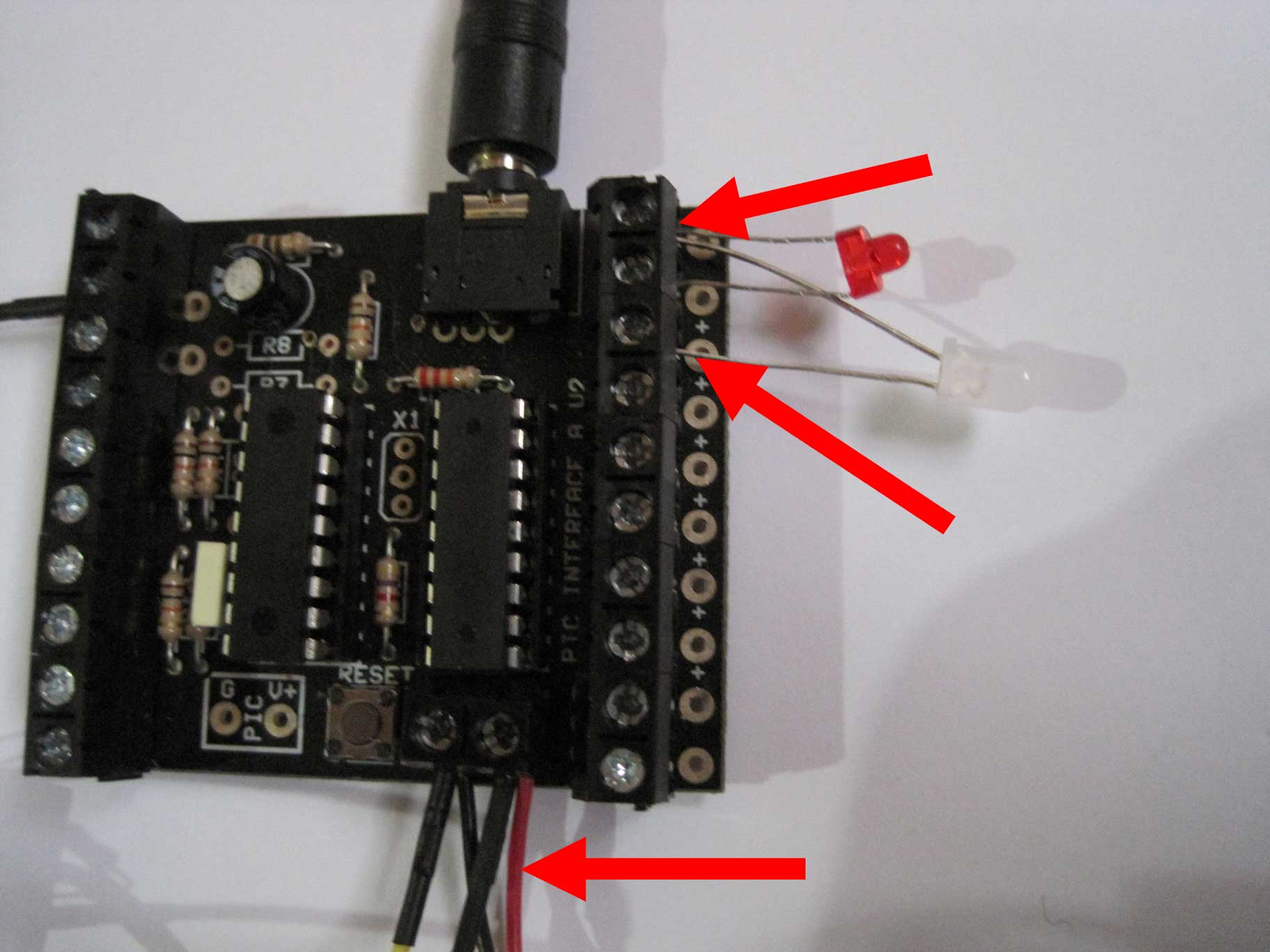
ALl the outputs are conviently setup on the right hand side of the developer with OUTPUT7 at the top (second connection) and OUTPUT0 at the bottom (second last connection). The very first connection at the top of the board is the positive supply and the last connection is the negative supply.
(1) Insert an LED with the negative lead (indified by a shorter lead and also has a flat egde on the body into the OUTPUT7 terminal block and insert the other end into the positive supply rail.NOTE: The circuit diagram previously shown had resistors inserted in series with the LEDs to restrict current, these are not used here because typically a PICAXE can only supply 15-20mA of current which is what the LEDs run at so in this instance the resistors are not needed.
(2) Do the same for the second LED, except insert the negative lead into OUTPUT6
(3) Insert the power wires from the battery pack into the power terminals (at the bottom of the board)
Next Step
|